If you open the device, you can access 2 sets of GPIO pins.
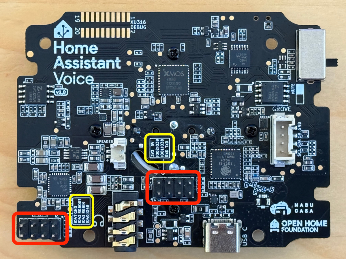
Notice
Opening the device and connecting to the GPIO pins voids the warranty.
About the GPIO pins
GPIO pin header group 1
Pin header in corner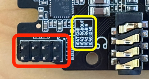
- Pin assignments:
IO47,GNDIO42,RGBOUTIO41,RGBINIO40,IO48
- Notice: Risk of damaging VPE components due to high current.
- Current drawn from GPIO pins should be limited to 20 milliamps (mA) or damage to the ESP32-S3 may occur.
- RGBIN/RGBOUT pins:
- The RGBIN/RGBOUT pins are connected to the LEDs in the LED ring on top.
- They could be used to connect additional WS2812-type LEDs.
- RGBIN is connected to the input of the first LED in the ring.
- RGBOUT is connected to the output from the last LED in the ring.
GPIO pin header group 2
Pin header in board center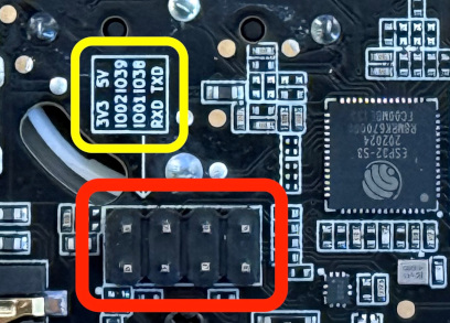
- Pin assignments:
+3.3 V,+5 VIO02,IO39IO01,IO38RXD,TXD
- Power pins (+5 V, +3.3 V):
- Notice: Risk of damaging VPE components due to high current.
- Mind the power limitations
- The amount of power you can draw from the power pins (+5 V, +3.3 V) on these headers depends on the capabilities of the power supply you are using; most common USB power supplies can supply either 1, 2, or 3 amps.
- Reputable power supplies will be labeled with their capabilities (voltage, current).
- Regardless of the power supply, do not attempt to draw more than 2 amps (total) from the +5 V and +3.3 V pins. Drawing more current than this from these pins may cause damage to components in the VPE, causing it to stop working.
- Mind the power limitations
- Notice: Risk of damaging VPE components due to high current.
- ESP32-S3 TXD and RXD pins:
- The ESP32-S3’s U0TXD and U0RXD (serial/UART) pins are not used by the firmware shipped with the VPE.
- If you want to watch logs and/or reinstall the ESP32-S3, use the built-in USB port.
GPIO pin header group 3
Grove port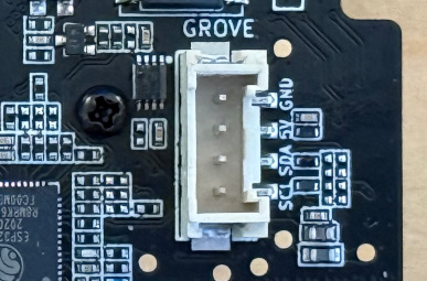
- Pin assignments:
SCL,SDA,5V,GND - Notice: Risk of damaging VPE components due to high current.
- Current drawn from GPIO pins should be limited to 20 milliamps (mA) or damage to the ESP32-S3 may occur.
- +5V pin power switching:
- The Grove expansion port has a “load switch” on its +5 V pin.
- This is controlled by the ESP32-S3’s GPIO pin 46.
- Power is not available on the Grove port’s +5 V pin unless this GPIO pin is switched on (high).