Follow these steps if you have 3D-printed your own enclosure parts and want to reassemble the device.
Notice
Disassembling Home Assistant Voice Preview Edition can void warranty.
Prerequisites
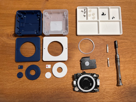
- Disassembled Home Assistant Voice Preview Edition
- Your own awesome 3D-printed parts
- No 2 crosshead screwdriver
- No 4 flathead screwdriver
Reassembling the device enclosure
Step 1
Place the rubber ring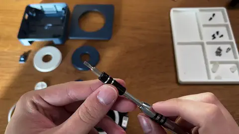
- Take the flathead screwdriver and remove the rubber ring from the button.
- The ring is glued to the button so this will be a bit sticky.
- Place the rubber ring onto the new button.
Step 2
Assemble button and dial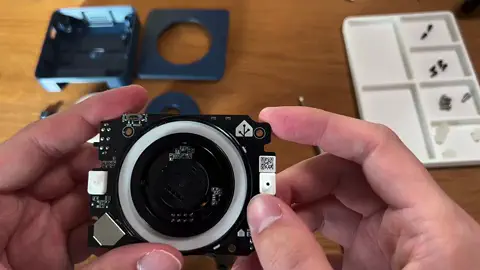
- Take note of the orientation of the rotary disk. Rotate until it is aligned as shown in the video.
- Place the button onto the rotary disk.
- Take the dial and take note of the square cutout. It must align with the button.
- Slide the dial onto the board and press until it clicks into place.
- Rotate the dial. It must rotate easily. If it does not, make sure it is not tilted.
Step 3
Place the LED diffuser ring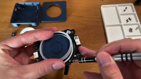
- The LED diffuser ring has a small latch. Make sure it aligns with the notch in the board.
- Gently press the LED diffuser ring until it clicks into place.
Step 4
Attach the speaker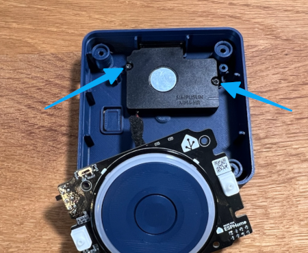
- Take the crosshead screwdriver and attach the speaker with the 2 screws.
Step 5
Attach the mute switch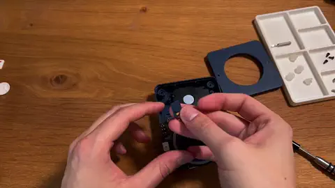
- Attach the mute switch.
- Mind the orientation. The colored part should face the middle, not the corner.
- Find the switch opening in the case.
- Slide the board into the case. Make sure the switch goes through the opening.
Step 6
Attach the PCB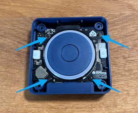
- Take the crosshead screwdriver and the 4 screws and attach the PCB.
Step 7
Place the top cover onto the device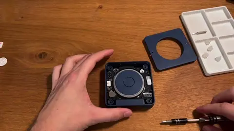
- Pick up the top cover and orient it to fit the case.
- The 2 holes should be above the microphones.
- Watch out for the side with the wider border.
- Slide the top cover onto the device.
Step 8
Close the enclosure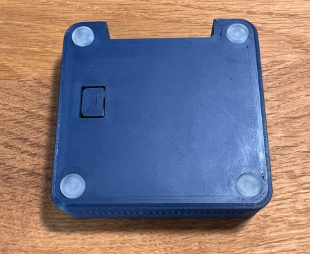
- Take the crosshead screwdriver and the 4 screws and close the enclosure.
- Place the rubber feet.
Step 9
Done!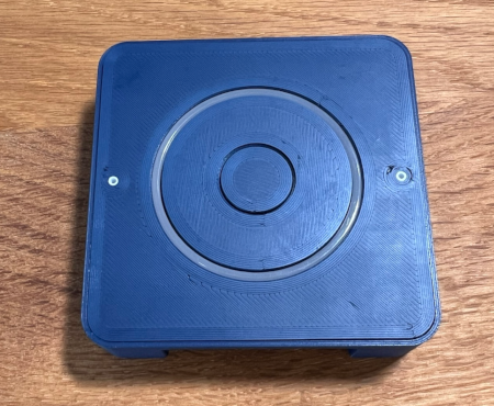
- Connect a USB-C power supply and continue using the device.